Normal Surfaces - Definition
We begin this visualization process with a discussion of normal surfaces
only. Recall our definition of the six principal projection planes: Front,
Back, Top, Bottom, Left, Right. A normal surface is a
surface that is perpendicular to two of the principal planes and parallel to
the third. To illustrate the simplest example of normal surfaces, we will use a
rectangular block.
The following site is a fairly comprehensive study of the "Normal surface". Most of the images shown below are excerpts from this site. The site is actually quite good and I encourage you to view it thoroughly after a brief review of the images/definitions below.
Normal Surfaces in Orthographic Projection site
The key phrase for this lesson - as well as the companion lessons on inclined, oblique and cylindrical surfaces -- IS VISUALIZE.
Visualization Process
The ability to form a mental picture of an object from a drawing is not
acquired all at once; it must be accomplished gradually. As with the study of
any language for communication, we must first learn the simple words and
phrases. So in visualizing an object we must start with lines and plane
surfaces on simple objects before we progress to more complex objects.
You must develop the ability to "read" each feature of the object by interpreting the information given within the drawing. This ability will help you to visualize the shape of objects. Rather than staring at orthographic views in an attempt to visualize the object, consider the technique of reading the lines and areas. Each area can represent a surface, while each line on the object can represent either the line view of a surface, or the edge intersection of two surfaces.
Normal Surfaces - Definition
We begin this visualization process with a discussion of normal surfaces
only. Recall our definition of the six principal projection planes: Front,
Back, Top, Bottom, Left, Right. A normal surface is a
surface that is perpendicular to two of the principal planes and parallel to
the third. To illustrate the simplest example of normal surfaces, we will use a
rectangular block.
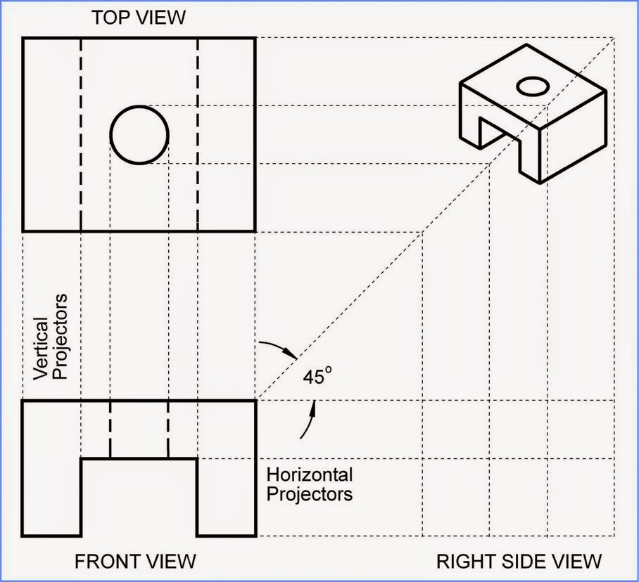
Now what this means in respect to the figure below is that the top surface is NORMAL to the "front" view and the "right" view while the top surface is parallel to the "top surface plane".

The image below left is an isometric view while the image below right is an orthographic view.


In Example N-1 below, surface A and edge A are identified in the isometric
(3D pictorial) view. Identify the same surface and the same edge in each
of the three orthographic views (front, top, and side) provided.
Surface A is shown "True size" because surface A is parallel with the "frontal surface plane", while surface A is also perpendicular to the other two "surface planes" - in this case the top surface plane and the right surface plane. The result is that surface A is normal (at a 90 degree angle) to the top and the right side surface planes. This is "pictured" for us as surface A and is True sized while the top and right views of "surface A" are simply LINES both of which are also true sized.

Now look at the solution of the same surface and the same edge.
Notice that the surface A appears as an area in the front orthographic
view. Surface A is parallel to the frontal projection plane, and
therefore it appears true size (TS) in that view.
Surface A is
perpendicular to both the horizontal and profile projection planes, and
therefore appears as a line in those views.
Now you may have a tendency to "get confused" by the terms "frontal, horizontal and profile" projection planes. The frontal projection plane simply refers to "the surface plane" upon which the front view lies completely flat (this is the meaning of "parallel" with this plane)
The horizontal projection plane refers to the horizontal plane that is perpendicular to the frontal projection plane (the top view) and the profile projection plane (right view) refers to the OTHER projection plane that is perpendicular to the frontal projection plane.
This other plane is a vertical plane that is perpendicular to the frontal projection view while the previous perpendicular plane was in the horizontal direction.
Edge A appears as a line in
the front and top views. (Edge A is actually the intersection of the frontal and horizontal projection planes in respect to the boundaries of the object).
Edge A is parallel to the frontal and
horizontal projection planes and therefore appears true length (TL) in
those orthographic views. Edge A is perpendicular to the profile plane
and therefore appears as a point in that orthographic view.
Lab exercise: Using a standard sized sheet of paper sketch an isometric view of a rectangular block as shown in example N-1.
1) Shade surface A and number the four corners of surface A (1,2,3,4) as shown in red above. Put these numbers in the proper corners of the isometric view that you have drawn.
2) Add numbers 5 and 6 to the proper "place" next to numbers you have labeled as the corners of surface A on the isometric view.
3) Add numbers 9 and 10 to the isometric view in the same manner as step 2.
Answers to Lab exercise: The upper left corner should be labeled (9,1). The upper right corner should be labeled (2,10,5). The lower left corner should be labeled (4 only). and the lower right corner should be labeled (3.6).
Now to turn in for a grade, I want you to repeat this procedure with Surface B as shown in example N-2.
1) Letter your name, section number and seat number in the upper right hand corner of your paper.
2) Using a pencil, provide an isometric sketch of the rectangular block shown in example N-2.
3) On the isometric view that you have sketched, label each corner of surface B using the numbering system shown in this example.
For the following - place the numbers in the proper location (just like the practice problem above)
a) show the corners 9,10,11,12
b) show the line (1,2)
c) show the line (5,8)
Another example: N-2

In Example N-2, surface B and edge B are identified in the
isometric (3D pictorial) view. Identify the same surface and the same
edge in each of the three orthographic views (front, top, and side)
provided.

Notice that the surface B appears as an area in the top orthographic
view. Surface B is parallel to the horizontal projection plane, and
therefore it appears true size (TS) in the top view. Surface B is
perpendicular to both the frontal and profile projection planes, and
therefore appears as a line in those views.
Edge B appears as a line in the top and side views. Edge B is parallel to the horizontal and profile projection planes and therefore appears true length (TL) in those orthographic views. Edge B is perpendicular to the frontal plane and therefore appears as a point in that orthographic view.
Edge B appears as a line in the top and side views. Edge B is parallel to the horizontal and profile projection planes and therefore appears true length (TL) in those orthographic views. Edge B is perpendicular to the frontal plane and therefore appears as a point in that orthographic view.

In Example N-3, surface C and edge C are identified in the
isometric (3D pictorial) view. Identify the same surface and the same
edge in each of the three orthographic views (front, top, and side)
provided.

Notice that the surface C appears as an area in the profile
(right-side) orthographic view. Surface C is parallel to the profile projection plane,
and therefore it appears true size (TS) in the profile view.
Surface C is perpendicular to both the horizontal and frontal projection
planes, and therefore appears as a line in those views.
Edge C appears as a line in the front and side views. Edge C is parallel to the frontal and profile projection planes and therefore appears true length (TL) in those orthographic views. Edge A is perpendicular to the horizontal plane and therefore appears as a point in that orthographic view.
Edge C appears as a line in the front and side views. Edge C is parallel to the frontal and profile projection planes and therefore appears true length (TL) in those orthographic views. Edge A is perpendicular to the horizontal plane and therefore appears as a point in that orthographic view.
Normal Surfaces in Orthographic Projection

In the previous examples (N-1 through N-3), the normal surfaces that
were identified were all simple rectangular shapes. It is important to
realize that rules for normal surfaces apply regardless of the shape of the surface. A
normal surface of any shape will always appear as a line in two of the
principal views. It will always appear true size in the third view.

Surface A

Surface B

Surface C
To help us reinforce the concept that A
normal surface of any shape will always appear as a line in two of the
principal views. It will always appear true size in the third view, I want us to look at the Lego pictures.
 |
| frontal view |
 |
| Top View |
 |
| Profile or right view |
The point here is that while looking at the frontal view - the right (profile) view as well as the top view BOTH appear as only a line.
If we switch over and look look at the profile view - the same is true regarding both the top and the front views.
Switching to the top view - we can see that the front and the right side are both portrayed as only lines.
The images below will serve as an introduction to the next lesson (Inclined surfaces)

The remaining images can be viewed more completely (as well as other available features) on the link provided at the beginning of this post. They are provided below for your convenience as a quick review.
Normal surfaces in Orthographic Projections
Example N-5

In cases where the top and front views are given, a
good starting point is to identify those features which are visible in
the front and top views of the object, find the feature in the other
given view and then create their representations in the missing side
view. Assume that visible bounded areas represent normal surfaces.

The top of the object appears as a line (27,30) in the front view.
The top appears as an area (11,10,9,8,7,6,20,21,22,23,24,25) in the
top view. Projection of that surface into the side view gives a
horizontal line (A,B).
(Next think about the front surface(s) of the object.)

The front of the object appears as lines (24,25) and
(21,20) in the top view. There are two separate surfaces on the front. These two surfaces
appear as areas (27,28,43,42) and (29,30,31,44) in the front view.
Projection of those surfaces into the side view gives a vertical line
(A,C)
(Next look at the remaining visible areas in the front view, starting with (28,29,44,43))

Area (28,29,44,43) is a visible TS area in the front view. Line
(23,22) is the representation of that surface in the top view. Projection into the side
view gives line (A,B), a hidden line.
(Next look at area (42,31,34,35,36,37,38,39))

Area (42,31,34,35,36,37,38,39) is a visible TS area in the
front view. Line (26,19) is the line view of that surface. Projection into
the side view gives line (A,B).
(Next look at areas (41,42,39,40) and (31,32,33,34))

(31,32,33,34) is a visible area in the front
view. (6,5) is the line view of that surface in the top view.
(29,30,31,44) is a visible area in the front view. (7,6) is the line
view of that surface in the top view. Projection of these two surfaces
into
the side view gives line (A,B). Because of symmetry, areas (27,28,43,42)
and (41,42,39,40) could be treated the same way. When projected into
the right side vioew these surfaces would appear as a hidden line (A,B)
but due to the precedence of object lines, nothing else is added to the
side view.
(Next look at area (37,36,35,38))

The area (37,36,35,38) by orthographic reading
COULD be represented by line (18,17) or line (13,14). Since we have
already identified surface (42,31,34,35,36,37,38,39) as line (26,19),
surface (37,36,35,38) cannot be (18,17).
Surface (37,36,35,38) appears a line (13,14) in the top view.
Draw line (A,B) in the side view. Consider the visibility of that
line.
(Next look at remaining visible areas in the top view, starting with (3,4,5,7) and (1,2,10,12))

(3,4,5,7) appears as a TS area in the top view. It
appears
as edge (44,32) in the front. Projection gives line (A,B) in the side
view. Due to symmetry, this also accounts for surface (1,2,10,12).
Recognize that line 43,44 has not been accounted for. There is another
surface on the same height as the two shaded areas above. We will
remember this later.
(Next look at area (15,16,8,9)