Chapter Two of "Solid Modeling Text"
In this textbook tutorial - we will create a 2D drawing of the "flange" that we created previously. If you do not have a correct file of "the flange" follow the link provided. It will take you to a video which provides detailed instructions on how to make "the flange".
 Once "The Flange" has been created AND UNDERSTOOD proceed with the step by step instructions given beginning with the section "Engineering Drawings" of the SolidWorks textbook.
Open a new document using the "new document" tool. While viewing the menu that appears choose "DRAWING" and click OK.

The next thing to consider is the size of "the paper" upon which the drawing will appear. If you were making a drawing "the old fashioned" way, the first thing you would do, would be to decide what sized paper you would use.


It is important for you to realize that there are a varying number of paper sizes as well as the orientation of portrait and landscape. When the dialog box below pops up - UNCHECK the "only show standard formats" box. When you do this, a good many different sizes will appear in the dropdown menu. When each item is highlighted - the size of that choice will be displayed along with a preview.

QUESTIONS:
1) Explain what the phrase "The drawing will be fully associative with the part file . . ." means.
2) What are the three chapter objects of the current chapter? You will 1) Make a 2D drawing from a SolidWorks part, 2) create a custom drawing sheet format, 3) Use eDrawings software to create a drawing file that allows for easy file sharing and collaborative editing.
3) What are the dimensions of ANSI C drafting paper? 17in x 22in or 431.8mm x 558.8mm.
4) In regard to the options tab - Do you remember the difference between "system properties" and "document properties"? Notice the changes requested in the text regarding items under the "system properties" tab. Will these changes only affect the current document or will they affect future documents until "edited"? The changes indicated will affect current and future documents. A change in "system properties" is a change for "the system" and will affect current and FUTURE documents until removed or changed. Edits in the "document properties" tab will ONLY affect the current document/session and WILL NOT remain in effect for future sessions as will the edits made in the SYSTEM PROPERTIES tab.
Make all of the recommended changes and proceed.


You might be concerned regarding the number of decimal places that we "set" during the previous instructions. What will happen if "our part" or model has been drawn with a different accuracy? Do not be concerned, setting the decimal places in our "document properties" tab will not affect the accuracy of the model, it will only affect the way the dimensions are DISPLAYED.
Please make a note of the difference between first and third angle projection.


Remember that when you select "options" - the changes that you make on the 'system options' tab will apply to FUTURE sessions, but those changes made under the 'document properties' tab will revert to their PREVIOUS values UNLESS SAVED.

 When you follow the SAVE AS step in this tutorial BE SURE that you put the new file in a place that you can find. You might want to pay attention to the location, because you will be required to find it and use it again later.
 RIGHT-CLICK on any of
the CommandManager tabs. Click on the name
of each group OTHER than View Layout, Annotation, and Sketch in order to CLEAR
the check mark and turn off the display of that group.
RIGHT-CLICK on any of
the CommandManager tabs. Click on the name
of each group OTHER than View Layout, Annotation, and Sketch in order to CLEAR
the check mark and turn off the display of that group.
 If you have already opened THE FLANGE then it will appear as shown in the figure to the right. If it does not appear then use the BROWSE button to look for it where you have previously stored it.
You will notice that the front ant top views are "greyed out", this indicates that they have been SELECTED. Also notice the items under "more views" at the bottom of the image, these may be checked if you desire to add them to the drawing.
One more thing to consider on this image are the two squares to the right of the image. This is where the selected views will actually be placed on the drawing.
hhh

The image below is what resulted when the green check-mark above is selected .

If you want to "reposition" the views move the mouse cursor over the rectangular box that surrounds the view. A MOVE ARROW will appear allowing you to "reposition" the views. You will not be able to separate the views from one another because they will move TOGETHER.
Drawing SCALE: The scale was selected automatically so that the views fit on the sheet that you have chosen. If you want to change the SCALE, then RIGHT CLICK in the graphic area and select PROPERTIES to define a new scale. The figure below is the menu that appears when properties is selected as instructed.

The next item that we will cover is ADDING DIMENSIONS to our drawing. We can use the smart dimension tool to do this OR we can IMPORT the dimensions from the part model where we got the views from.
The later is the preferred method because we can change the dimensions AND if we import them from the model then these changes will be REFLECTED in the model.
Dimensions that we add with the SMART DIMENSION tool will be DRIVEN dimensions. This means that their value WILL CHANGE or be updated when changes are made to the model BUT this also means that the DRIVEN dimension cannot be used to change the dimensions on the model.
 The driven dimensions are like a ONE WAY street. The changes made on the model will update the driven dimensions in the drawing, but the changes to the driven dimensions on the drawing WILL NOT update on the model. The drawing can be changed from the model, but the model cannot be changed from the drawing.

In the figure "Imported Dimensions" you will notice that the dimension placement needs to be corrected. This is accomplished by simply clicking and dragging to a new location. Remember our lessons on "Dimension Placement"?
Practice placing the dimensions in their proper arrangement. The dimensions should not be placed in a way that is confusing or hard to read. They should be placed similarly to what is seen in the image "repositioned dimensions".
You can also change the direction of the arrows on linear measurements. This can be accomplished by clicking ONCE on the dimension and THEN clicking a second time on the GREEN DOTS that appear on the arrow heads. Clicking on these green dots will switch the direction of the arrow heads from inside to outside and back again.
If you remembered our lesson on proper dimension placement, then perhaps you are wondering why we have not followed "standard drawing practice" regarding the placement of these dimensions.
When diameters of a solid cylindrical feature is shown - this dimension SHOULD be shown in a view that is NORMAL to the view in which the feature appears as a circle.
What this means in regard to our "repositioned dimensions" is that the diameter of 5.50" should NOT appear in the front view, but it should be placed in the TOP view.
Notice the two dimensions that we moved in the figure"Move Diameter Dimensions". We did this by PRESS AND HOLD the SHIFT key WHILE dragging the dimension to the TOP view.
This MOVES the dimension that was on the front view to the TOP view as indicated in the image above.
 Another "standard drawing practice" is that hole diameters should be shown with LEADERS rather than as linear dimensions. To accomplish this notice the two dimensions in the figure above that are listed as linear dimensions using extension lines Ø 1.50 and Ø .50 . Follow the procedure given here to "change" from extension lines to leader lines.


 You will notice that there are no dimensions on this DETAIL VIEW, but they can be imported from the model view. The
measurement of the chamfer is 45° but this measurement is not shown. The following procedure will show how to
import this dimension from the part model.
You will notice that there are no dimensions on this DETAIL VIEW, but they can be imported from the model view. The
measurement of the chamfer is 45° but this measurement is not shown. The following procedure will show how to
import this dimension from the part model.
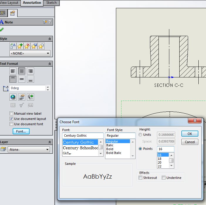 To change the font of the labels of the sectional or detail views all you need to do is to click on the text you want to change. The PropertyManager will appear with the option shown in the accompanying image.
Make the changes indicated. When you select the "Use document layout" box it activates the font button. Use this to make desired changes.
If you want to actually change the TEXT and rename the views from A-A to W-W or add to the word "detail" then do the following"
RIGHT CLICK on the text. A menu will appear with various options - select "edit text" and the text will appear in a box and you can make any changes you want.

 Often it is more critical to hold certain dimensions to a tighter tolerance than others. This means that we will need to SPECIFY specific tolerance values for some of the dimensions.

Click on the numeric value of a dimension as shown here. When you do this a small icon like the one shown will appear. The next action for you to take is to put your cursor over this icon and the result will be that the image above will appear. It is from this pop-up that you will be able to make edits to the style of the specified dimension.
 A) Using the various "pull downs" change the number of decimal places to (.123).
B) Using another "pull down" set the tolerance type to BILATERAL.
C) Click on the numerical value of the plus tolerance and enter a value of .003.
Geometric Tolerancing: In the above example we chose to place a somewhat tight tolerance on the diameter of the center hole so that a tight fit would occur between the flange and the part that fits into the hole.
In a real life situation, how would we know what this tolerance should be? The correct answer is that the tolerance should be what is required for the part to function as designed.
The tolerance that is required will often determine the manufacturing process that is used to create the part. In "the real world" some manufacturing processes are obviously more economical than others, but the better economy may not produce the type of tolerance that is required. This leads to "added steps" afterward which offset the cheaper initial cost.
The process of GD&T (Geometric Dimensioning and Tolerancing) allows a designer to specify the "acceptable condition" of a part in regard to its function.
Some examples of this might be 1) a hole diameter and 2) a diameter of a pin that fits into the hole. We could provide the necessary tolerances so that the pin would fit into the hole with proper clearance BUT what if the pin was slightly bent? To ensure that the pin would fit EVEN if the sizes were within tolerance - we would need to ADD an additional tolerance of FLATNESS to the pin geometry.
Proper application of GD&T standard can actually reduce the cost of making may parts since they allow for the CONTROL of the important features of a part more efficiently than simply tightening the tolerance values of ALL DIMENSIONS.
In the given image, we are going to apply Geometric Tolerancing.
In the image shown (the top view) click on the line representing THE BACK surface of the flange. THEN select the GEOMETRIC TOLERANCE TOOL from the annotation group of the CommandManager.
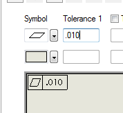 In the dialog box that appears, select the FLATNESS SYMBOL from the pull down menu. Enter the value 0.010 as the value for Tolerance 1 and a preview of the tolerance call-out will appear.
Click to place the annotation in the desired location. Click OK
to apply the tolerance . . .


Adding Notes: Select the NOTE TOOL from the Annotation group of the CommandManager.
 Drag the cursor to the approximate location where the note is to be placed. DO NOT click directly on an item in the drawing OR the note will appear with a leader line to that item. Choose the font type and size from the toolbar that appears. In the text box that appears at the location you chose, begin typing the text of the notes you want to add.
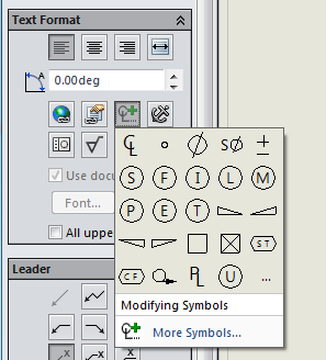
To add a symbol to your note: Under the "text format" heading that appears in the CommandManager chose the ADD SYMBOL icon and click your choice.
In this textbook tutorial - we will create a 2D drawing of the "flange" that we created previously. If you do not have a correct file of "the flange" follow the link provided. It will take you to a video which provides detailed instructions on how to make "the flange".
Open a new document using the "new document" tool. While viewing the menu that appears choose "DRAWING" and click OK.
The next thing to consider is the size of "the paper" upon which the drawing will appear. If you were making a drawing "the old fashioned" way, the first thing you would do, would be to decide what sized paper you would use.
It is important for you to realize that there are a varying number of paper sizes as well as the orientation of portrait and landscape. When the dialog box below pops up - UNCHECK the "only show standard formats" box. When you do this, a good many different sizes will appear in the dropdown menu. When each item is highlighted - the size of that choice will be displayed along with a preview.
QUESTIONS:
1) Explain what the phrase "The drawing will be fully associative with the part file . . ." means.
2) What are the three chapter objects of the current chapter? You will 1) Make a 2D drawing from a SolidWorks part, 2) create a custom drawing sheet format, 3) Use eDrawings software to create a drawing file that allows for easy file sharing and collaborative editing.
3) What are the dimensions of ANSI C drafting paper? 17in x 22in or 431.8mm x 558.8mm.
4) In regard to the options tab - Do you remember the difference between "system properties" and "document properties"? Notice the changes requested in the text regarding items under the "system properties" tab. Will these changes only affect the current document or will they affect future documents until "edited"? The changes indicated will affect current and future documents. A change in "system properties" is a change for "the system" and will affect current and FUTURE documents until removed or changed. Edits in the "document properties" tab will ONLY affect the current document/session and WILL NOT remain in effect for future sessions as will the edits made in the SYSTEM PROPERTIES tab.
Make all of the recommended changes and proceed.
You might be concerned regarding the number of decimal places that we "set" during the previous instructions. What will happen if "our part" or model has been drawn with a different accuracy? Do not be concerned, setting the decimal places in our "document properties" tab will not affect the accuracy of the model, it will only affect the way the dimensions are DISPLAYED.
Please make a note of the difference between first and third angle projection.

Remember that when you select "options" - the changes that you make on the 'system options' tab will apply to FUTURE sessions, but those changes made under the 'document properties' tab will revert to their PREVIOUS values UNLESS SAVED.
When you follow the SAVE AS step in this tutorial BE SURE that you put the new file in a place that you can find. You might want to pay attention to the location, because you will be required to find it and use it again later.RIGHT-CLICK on any of
the CommandManager tabs. Click on the name
of each group OTHER than View Layout, Annotation, and Sketch in order to CLEAR
the check mark and turn off the display of that group.
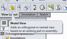
From the VIEW LAY OUT
tab of the CommandManager select the MODEL VIEW TOOL as shown.
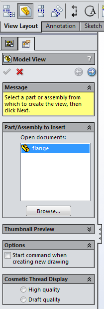
If you have already opened THE FLANGE then it will appear as shown in the figure to the right. If it does not appear then use the BROWSE button to look for it where you have previously stored it.
Double click the file
name. The PropertyManager will change to
the view shown. Check the CREATE
MULITPLE VIEWS box. Click on the TOP and
FRONT views. Then click the green
check-mark to place the views.
You will notice that the front ant top views are "greyed out", this indicates that they have been SELECTED. Also notice the items under "more views" at the bottom of the image, these may be checked if you desire to add them to the drawing.
One more thing to consider on this image are the two squares to the right of the image. This is where the selected views will actually be placed on the drawing.
hhh
The image below is what resulted when the green check-mark above is selected .
If you want to "reposition" the views move the mouse cursor over the rectangular box that surrounds the view. A MOVE ARROW will appear allowing you to "reposition" the views. You will not be able to separate the views from one another because they will move TOGETHER.
Drawing SCALE: The scale was selected automatically so that the views fit on the sheet that you have chosen. If you want to change the SCALE, then RIGHT CLICK in the graphic area and select PROPERTIES to define a new scale. The figure below is the menu that appears when properties is selected as instructed.
The next item that we will cover is ADDING DIMENSIONS to our drawing. We can use the smart dimension tool to do this OR we can IMPORT the dimensions from the part model where we got the views from.
The later is the preferred method because we can change the dimensions AND if we import them from the model then these changes will be REFLECTED in the model.
Dimensions that we add with the SMART DIMENSION tool will be DRIVEN dimensions. This means that their value WILL CHANGE or be updated when changes are made to the model BUT this also means that the DRIVEN dimension cannot be used to change the dimensions on the model.
The driven dimensions are like a ONE WAY street. The changes made on the model will update the driven dimensions in the drawing, but the changes to the driven dimensions on the drawing WILL NOT update on the model. The drawing can be changed from the model, but the model cannot be changed from the drawing.
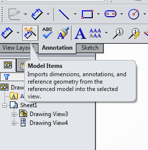
Click the ANNOTATION
TAB of the CommandManager and select the MODEL ITEMS TOOL in the
PropertyManager. Make the changes
indicated. Entire model as the
source. Check boxes labeled “Import
items into all views” and “Eliminate duplicates”. Finally click the Green check-mark to import
the dimensions into the drawing.
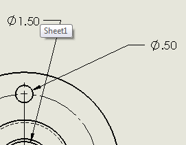
In the figure "Imported Dimensions" you will notice that the dimension placement needs to be corrected. This is accomplished by simply clicking and dragging to a new location. Remember our lessons on "Dimension Placement"?
 |
| Imported Dimensions |
Practice placing the dimensions in their proper arrangement. The dimensions should not be placed in a way that is confusing or hard to read. They should be placed similarly to what is seen in the image "repositioned dimensions".
 |
| Repositioned Dimensions |
You can also change the direction of the arrows on linear measurements. This can be accomplished by clicking ONCE on the dimension and THEN clicking a second time on the GREEN DOTS that appear on the arrow heads. Clicking on these green dots will switch the direction of the arrow heads from inside to outside and back again.
If you remembered our lesson on proper dimension placement, then perhaps you are wondering why we have not followed "standard drawing practice" regarding the placement of these dimensions.
 |
| Move Diameter Dimensions |
When diameters of a solid cylindrical feature is shown - this dimension SHOULD be shown in a view that is NORMAL to the view in which the feature appears as a circle.
What this means in regard to our "repositioned dimensions" is that the diameter of 5.50" should NOT appear in the front view, but it should be placed in the TOP view.
Notice the two dimensions that we moved in the figure"Move Diameter Dimensions". We did this by PRESS AND HOLD the SHIFT key WHILE dragging the dimension to the TOP view.
This MOVES the dimension that was on the front view to the TOP view as indicated in the image above.
Another "standard drawing practice" is that hole diameters should be shown with LEADERS rather than as linear dimensions. To accomplish this notice the two dimensions in the figure above that are listed as linear dimensions using extension lines Ø 1.50 and Ø .50 . Follow the procedure given here to "change" from extension lines to leader lines.
Right Click on the value and a menu will appear, choose display options in this menu and then select "display as diameter". Then all that remains is for you to click and drag the dimension to a new location . . ."
The last thing we will look at regarding the placement of dimensions will deal with the Ø 4.25 diameter that is displayed as a linear dimension. We can change the ORIENTATION of a dimension the following way: Click the chosen dimension - a green dot will appear just above "the value" - place your cursor on this green dot - you will notice that a rotation symbol appears.
When the rotate symbol is active, you can drag "rotate" this dimension to a new location.
The options for changing the appearance of dimensions, dimension lines, and leaders are many so remember that the changes available for you to make are NOT LIMITED to those that we have covered in this lesson.
By right clicking on any dimension and selecting DISPLAY OPTIONS or PROPERTIES you will find that it is easy to change the appearance of any dimension.
The FONT style and size can both be changed from the PropertyManager Design Tree. Right Click on a dimension value the PropertyManager Design Tree will change as shown.
To change the font style or size, click on the "other" tab and enter the changes you desire under the heading "Text Fonts".
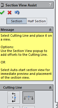
Sectional View: Click the VIEW LAYOUT TAB on the CommandManager
and select the SECTION VIEW TOOL.
In the PropertyManager
make certain that SECTION is selected.
Select the HORIZONTAL option.
After completing the instructions above - Move the cursor into the FRONT view and a PREVIEW of the section line will appear.
Move the cursor to the CENTER MARK of the view. This will cause the section to pass through this point. Move and click to place.
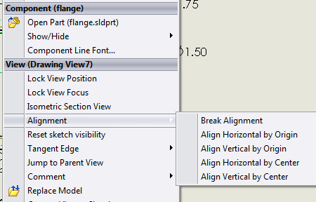
Unless you want to locate the sectional view "in line" with both the front and top views you will need to "Break" the alignment so you can move the sectional view to a new location "beside the front and top views.
With the cursor in the graphics area over the sectional view RIGHT CLICK. A menu will appear as shown. Choose "alignment" then choose "break alignment". Now you can drag and drop the sectional view to a new location.
There may be occasions when you want to change a "line style" of a section or other type of line. This can be accomplished by Selecting OPTIONS TOOL - DOCUMENT PROPERTIES - VIEWS . . . as seen the the image shown.
Center-lines can be removed by clicking and deleting OR center-lines can be added by using the CENTER-LINE TOOL
in the Annotation Tab of the CommandManager.
 |
| Add Center-Line |
Hidden edges are not typically shown in sectional views - but the option of placing them in any view is available. This can be done by selecting the view and then choosing the display STYLE in the HEADS UP VIEW TOOLBAR.
DETAIL VIEW: When this tool is activated the CIRCLE TOOL becomes active.
Drag out a circle around the area you want to include in the DETAIL VIEW. Move the cursor to the position where you want the DETAIL VIEW to appear on the drawing and click to place.
The DETAIL VIEW has been given a scale of 1:1 but this can be changed to enlarge the area further.
Select the DETAIL VIEW with the cursor. The PropertyManager Design Tree will appear. In the PropertyManager Design Tree area select the "Use custom scale" option. A drop-down will become active and you can choose 2:1 or what-ever you want.
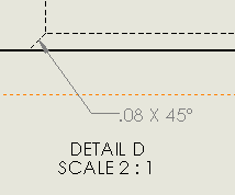
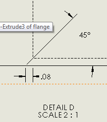
You will notice that there are no dimensions on this DETAIL VIEW, but they can be imported from the model view. The
measurement of the chamfer is 45° but this measurement is not shown. The following procedure will show how to
import this dimension from the part model.
Click inside the DETAIL VIEW then select the Annotation Tab in the CommandManager. From this select the MODEL ITEMS TOOL. Now to complete this step click on the check-mark and you are done.
When I followed this procedure I got an error message telling me that the dimension could not be imported. So what I did was this: I activated the SMART DIMENSION TOOL and placed the dimension in the desired location as shown in the image.
The error message mentioned "Section C-C" - so I selected section C-C and repeated the procedure - it worked and imported the 45 degree dimension to the sectional view. I then used the "SHIFT" key and moved it to the DETAILED VIEW.
You will notice that the dimension is a slightly different color. This indicates that because we placed it in the view FROM the drawing that it is a DRIVEN dimension. Remember that this means that the model dimensions cannot be changed from the drawing BUT rather the drawing dimensions can be changed (updated) from the model.
To change the font of the labels of the sectional or detail views all you need to do is to click on the text you want to change. The PropertyManager will appear with the option shown in the accompanying image.Make the changes indicated. When you select the "Use document layout" box it activates the font button. Use this to make desired changes.
If you want to actually change the TEXT and rename the views from A-A to W-W or add to the word "detail" then do the following"
RIGHT CLICK on the text. A menu will appear with various options - select "edit text" and the text will appear in a box and you can make any changes you want.
Often it is more critical to hold certain dimensions to a tighter tolerance than others. This means that we will need to SPECIFY specific tolerance values for some of the dimensions. Click on the numeric value of a dimension as shown here. When you do this a small icon like the one shown will appear. The next action for you to take is to put your cursor over this icon and the result will be that the image above will appear. It is from this pop-up that you will be able to make edits to the style of the specified dimension.
A) Using the various "pull downs" change the number of decimal places to (.123).B) Using another "pull down" set the tolerance type to BILATERAL.
C) Click on the numerical value of the plus tolerance and enter a value of .003.
Geometric Tolerancing: In the above example we chose to place a somewhat tight tolerance on the diameter of the center hole so that a tight fit would occur between the flange and the part that fits into the hole.
In a real life situation, how would we know what this tolerance should be? The correct answer is that the tolerance should be what is required for the part to function as designed.
The tolerance that is required will often determine the manufacturing process that is used to create the part. In "the real world" some manufacturing processes are obviously more economical than others, but the better economy may not produce the type of tolerance that is required. This leads to "added steps" afterward which offset the cheaper initial cost.
The process of GD&T (Geometric Dimensioning and Tolerancing) allows a designer to specify the "acceptable condition" of a part in regard to its function.
Some examples of this might be 1) a hole diameter and 2) a diameter of a pin that fits into the hole. We could provide the necessary tolerances so that the pin would fit into the hole with proper clearance BUT what if the pin was slightly bent? To ensure that the pin would fit EVEN if the sizes were within tolerance - we would need to ADD an additional tolerance of FLATNESS to the pin geometry.
 |
| Top View of Flange |
In the given image, we are going to apply Geometric Tolerancing.
 |
| Geometric Tolerance Tool |
 |
| Tolerance Symbols |
In the dialog box that appears, select the FLATNESS SYMBOL from the pull down menu. Enter the value 0.010 as the value for Tolerance 1 and a preview of the tolerance call-out will appear.Click to place the annotation in the desired location. Click OK
to apply the tolerance . . .
Adding Notes: Select the NOTE TOOL from the Annotation group of the CommandManager.
Drag the cursor to the approximate location where the note is to be placed. DO NOT click directly on an item in the drawing OR the note will appear with a leader line to that item. Choose the font type and size from the toolbar that appears. In the text box that appears at the location you chose, begin typing the text of the notes you want to add.To add a symbol to your note: Under the "text format" heading that appears in the CommandManager chose the ADD SYMBOL icon and click your choice.
No comments:
Post a Comment