This page will serve as a lesson on how to create your first SolidWorks Model. We have previously discussed Orthographic projections and the different types of planes used in drafting. We have also discussed the standards which control the concept of properly dimensioning a part.
This page will take your skills beyond the HOW TO of simply "creating a SolidWorks part" to the HOW TO of creating a SolidWorks Model.
"This page" will be somewhat comprehensive on this subject of SolidWorks Modeling. I will however provide a "break" which will divide this page into separate lessons.
From this page I will provide links to various posts (and sometimes other site) which will give greater detail intended to better enhance your understanding. zzzzzzzzzz
I will begin by posting an number of questions. As you proceed through this tutorial you should look for the answers as you will be tested on them at a later time.
1) What is the file name in the referenced tutorial.
2) On the "sketch toolbar" what tool is used first.
3) How many options are given for "releasing" the corner rectangle tool?
4) In dimensioning the base, what do the colored tags show?
5) What happens when the mouse is hovered over one of the tags?
6) By double clicking a tag you can do what?
7) In this tutorial, why is the rectangle different colors?
8) What does constrain mean?
9) There are two ways to "resize" the rectangle - be prepared to describe them.
10) When we use the smart dimension tool and click on the top line of the rectangle, a dialog box.
should appear when we click above the line to place the dimension, if the dialog box does not
appear, what is the problem?
The next group of questions can be answered as you progress through the tutorial.
1) After the first command in this section, the view of the sketch changes to what?
2) What happens when you press "z" on the keyboard?
3) What happens when you press "shift+z"?
4) After clicking the green check-mark the sketch was ________ into the extrusion feature.
5) How do you modify a sketch after it has been absorbed?
Look for the answers to these questions as you work through part 3 of this lesson.
1) You click the front face of the model to _______ the sketch plane for the next feature.
2) The extruded boss/base icon is found where?
3) "Normal to" is found where?
4) "Circle" icon is found where?
5) Relative to the model, where is the pointer moved to see the current dimension?
6) What happens if we click the extruded boss/base without selecting a sketch plane as indicated
in step #1?
Look for the answers to these questions as you work through part 4 of this lesson.
1) Where does the first dimension place the center of the circle?
2) The circle turns black indicating what?
3) The term "fully defined" is found where on the screen?
4) What does this symbol/measurement mean?
 5) What is the unit of measure {ft, in mm etc} represented by the dimensions in this model?
Look for the answers to these questions as you work through part 5 of this lesson.
1) What is the first command on this part of the tutorial?
2) After clicking on exit sketch how does the view of the sketch change?
3) Where is the trimetric icon located?
Look for the answers to these questions as you work through part 6 of this lesson.
1) In this tutorial - the hole has a radius that measures how much less than the boss?
2) What is the first command of this tutorial?
3) In step #5 the change in the pointer indicates what?
4) In step #1 what happens if you do not select the front face before you click on the extruded cut
icon?
5) If you get this error message how do you exit and get back to where you were?
Look for the answers to these questions as you work through part 7 of this lesson.
1) In this tutorial, describe what happens after you click on the exit sketch in step #1.
2) What happens when you click on the "trimetric" icon?
3) The end condition of the boss is set to what choice in the drop down menu of the
property manager features tree?
Look for the answers to these questions as you work through part 8 of this lesson.
questions here.
1) Where is the fillet icon located?
2) To what feature does the radius of 5mm refer to?
3) What would happen if the four edges at the corners of the base were not selected?
4) In the property manager, what changes occur as the corners are selected?
Look for the answers to these questions as you work through part 9 of this lesson.
1) After clicking the fillet icon, the property manager changes. The top line contains "fillet",
there are five additional "titles" listed, what are they?
2) To what value is the radius set in step #2 (include units}?
3) Name the two fillets that are on the boss?
4) Rotate the part and look a the back side which is flat, are there any fillets there?
5) How many edges did you fillet?
Look for the answers to these questions as you work through part 10 of this lesson.
1) Name the different key-strokes that can be used to "release a tool".
2) What does the "shell" command do to the part?
3) What is the thickness of the remaining shell?
Look for the answers to these questions as you work through part 11 of this lesson.
1) What happens when you click on the "Trimetric" icon?
2) If the section view is not visible, how is it made visible?
On this one, the tutorial is a bit off. Obtain the view shown in the figure above and then with the mouse highlight the feature to be modified as shown below.
If the feature is to be deleted (after highlighting) use the delete key on the keyboard and just delete it.
If you want to edit a feature that you have selected, then using the edit feature icon on the pop-up that will appear when you "Click" on the feature, edit it as required.
Or you can do much the same thing by double clicking on the descriptions in the feature manager design tree to do the same thing.

This part of the tutorial is not valid with the student version of Solid works. All you will be able to do here is to change the color of the part. Go ahead and practice this.
This page will take your skills beyond the HOW TO of simply "creating a SolidWorks part" to the HOW TO of creating a SolidWorks Model.
"This page" will be somewhat comprehensive on this subject of SolidWorks Modeling. I will however provide a "break" which will divide this page into separate lessons.
From this page I will provide links to various posts (and sometimes other site) which will give greater detail intended to better enhance your understanding. zzzzzzzzzz
 |
| Click on image to go to Post with further instructions |
I will begin by posting an number of questions. As you proceed through this tutorial you should look for the answers as you will be tested on them at a later time.
Dimensioning the Base
 |
| The Product of "Dimensioning the base" |
1) What is the file name in the referenced tutorial.
2) On the "sketch toolbar" what tool is used first.
3) How many options are given for "releasing" the corner rectangle tool?
4) In dimensioning the base, what do the colored tags show?
5) What happens when the mouse is hovered over one of the tags?
6) By double clicking a tag you can do what?
7) In this tutorial, why is the rectangle different colors?
8) What does constrain mean?
9) There are two ways to "resize" the rectangle - be prepared to describe them.
10) When we use the smart dimension tool and click on the top line of the rectangle, a dialog box.
should appear when we click above the line to place the dimension, if the dialog box does not
appear, what is the problem?
The next group of questions can be answered as you progress through the tutorial.
Extruding the Base
 |
| Product of "Extruding the Base" |
1) After the first command in this section, the view of the sketch changes to what?
2) What happens when you press "z" on the keyboard?
3) What happens when you press "shift+z"?
4) After clicking the green check-mark the sketch was ________ into the extrusion feature.
5) How do you modify a sketch after it has been absorbed?
Look for the answers to these questions as you work through part 3 of this lesson.
Sketching and Dimensioning the Boss
 |
| Product of "Sketching and Dimensioning the Boss" |
1) You click the front face of the model to _______ the sketch plane for the next feature.
2) The extruded boss/base icon is found where?
3) "Normal to" is found where?
4) "Circle" icon is found where?
5) Relative to the model, where is the pointer moved to see the current dimension?
6) What happens if we click the extruded boss/base without selecting a sketch plane as indicated
in step #1?
Look for the answers to these questions as you work through part 4 of this lesson.
Constraining the Boss
 |
| Product of "constraining the Boss" |
1) Where does the first dimension place the center of the circle?
2) The circle turns black indicating what?
3) The term "fully defined" is found where on the screen?
4) What does this symbol/measurement mean?
Look for the answers to these questions as you work through part 5 of this lesson.
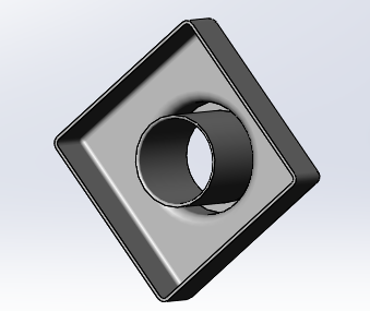
Extruding the Boss
 |
| Product of "Extruding the Boss" |
1) What is the first command on this part of the tutorial?
2) After clicking on exit sketch how does the view of the sketch change?
3) Where is the trimetric icon located?
Look for the answers to these questions as you work through part 6 of this lesson.
Sketching The Hole
 |
| Product of "Sketching the Hole" |
1) In this tutorial - the hole has a radius that measures how much less than the boss?
2) What is the first command of this tutorial?
3) In step #5 the change in the pointer indicates what?
4) In step #1 what happens if you do not select the front face before you click on the extruded cut
icon?
5) If you get this error message how do you exit and get back to where you were?
 |
| Error message see question 5 |
Look for the answers to these questions as you work through part 7 of this lesson.
Extruding the sketched hole
 |
| Product of "extruding the sketched hole" |
1) In this tutorial, describe what happens after you click on the exit sketch in step #1.
2) What happens when you click on the "trimetric" icon?
3) The end condition of the boss is set to what choice in the drop down menu of the
property manager features tree?
Look for the answers to these questions as you work through part 8 of this lesson.
questions here.
Creating the Base Fillets
 |
| Product of "Creating the Base Fillets" |
1) Where is the fillet icon located?
2) To what feature does the radius of 5mm refer to?
3) What would happen if the four edges at the corners of the base were not selected?
4) In the property manager, what changes occur as the corners are selected?
Look for the answers to these questions as you work through part 9 of this lesson.
Creating the Boss Fillets
 |
| Product of "Creating the Boss Fillets" |
1) After clicking the fillet icon, the property manager changes. The top line contains "fillet",
there are five additional "titles" listed, what are they?
2) To what value is the radius set in step #2 (include units}?
3) Name the two fillets that are on the boss?
4) Rotate the part and look a the back side which is flat, are there any fillets there?
5) How many edges did you fillet?
Look for the answers to these questions as you work through part 10 of this lesson.
Creating the shell
 |
| Product of "Creating the shell" |
1) Name the different key-strokes that can be used to "release a tool".
2) What does the "shell" command do to the part?
3) What is the thickness of the remaining shell?
Look for the answers to these questions as you work through part 11 of this lesson.
Creating a Section View of the shell
 |
| Product of "Creating a Section View of the shell" |
1) What happens when you click on the "Trimetric" icon?
2) If the section view is not visible, how is it made visible?
Editing the base feature:
 |
| Product of "editing the Base Feature" |
On this one, the tutorial is a bit off. Obtain the view shown in the figure above and then with the mouse highlight the feature to be modified as shown below.
 |
| Feature edit |
If you want to edit a feature that you have selected, then using the edit feature icon on the pop-up that will appear when you "Click" on the feature, edit it as required.
Or you can do much the same thing by double clicking on the descriptions in the feature manager design tree to do the same thing.
This part of the tutorial is not valid with the student version of Solid works. All you will be able to do here is to change the color of the part. Go ahead and practice this.
No comments:
Post a Comment