
Most engineering drawings include a TITLE BLOCK and a BORDER. The title block can include a large amount of information. In addition to basic data, such as the name of the part, the part number, the scale, the date created and so forth, many times the names and/or initials of the drafter/reviewers are required before the drawing is released to the end users.
The SolidWorks drawing program includes several default TITLE BLOCKS and BORDERS called sheet formats.
These SHEET FORMATS can be edited to fit the particular needs of the manufacturer. The sheet formats are different for every standard paper size. In this example we will create a simple sheet format for an A SIZE DRAWING.
 Open a NEW DRAWING. Choose "A-Landscape" as the paper size - Leave the "display sheet format" box UNCHECKED.
RIGHT-CLICK in the graphic area (the drawing space) and select "edit sheet format".

 To create the BORDER select the CORNER RECTANGLE TOOL from the sketch group of the CommandManager. Drag out the rectangle so that it fills out most of the page.
RIGHT-CLICK on the menu bar and select LINE FORMAT from the list of available tool bars.
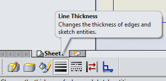
Select each segment of the rectangle and
then choose the thickest option for line thickness.
To locate the rectangle perform the following: Click on the lower left corner of the rectangle. In the PropertyManager you will be given the option of imputing the x and y coordinates of the corner you have selected.
After setting the coordinates of the lower left - set the x and y coordinates of the upper right. These values should be set as X = 10.625 inches and Y = 8.125 inches.
 |
| Lower Left coordinates |

Use the SMART DIMENSION TOOL to dimension the new rectangle at 3.5 inches by 1.4 inches.

Select the SMART DIMENSION TOOL and add the 1.1 inch and 1.4 inch dimensions.
Repeat this procedure to add the two
horizontal lines at .5 inch and .75 inch as shown.
 Obviously you do not want the dimensions to be displayed on your drawing so do the following: In the MAIN MENU choose "View" to reveal the menu containing "hide/show Annotation"
  |
| Hide/show Annotations |
After choosing this option - select the individual dimensions that you want to HIDE. The result will be as shown below. The "greyed out" dimensions will be hidden when you press ESC.
 |
| Select dimensions to hide or show |
Now we will ADD NOTES to the TITLE BLOCK. Select the NOTE TOOL from the Annotation group of the CommandManager
 After selecting the NOTE TOOL click in any space of the graphics area to place the note. Set the desired FONT and SIZE.
Type the text desired and drag the note into its final position.
Now we will add the scale value to the drawing and LINK it to the drawing sheets scale.
Open a NEW NOTE. In the PropertyManager select the LINK to property icon. From the pull-down select SW-Sheet Scale and click OK

 | |||
| SW Sheet Scale |
 Move the note to the proper place and pres ESC to end the note command. RIGHT CLICK in the drawing area and select "Edit Sheet". This action will cause a menu to appear - one of the options will be "properties" as shown:
Click on the properties option and make the choices indicated on the image below. When the proper options are selected click the OK button and the drawing with the different flange views will be applied to this drawing with the TITLE BLOCK and BOARDER.

Add current date, name and school name as instructed.
No comments:
Post a Comment