This page will serve as a lesson on how to create your first
SolidWorks part/drawing. We have previously discussed Orthographic projections
and the different types of planes used in drafting. We have also
discussed the standards which control the concept of properly
dimensioning a part.
This page will take your skills beyond the HOW TO of simply "representing three dimensional objects in two dimensional space" to the HOW TO of creating a SolidWorks part/drawing of such a representation.
"This page" will be somewhat comprehensive on this subject of SolidWorks part Modeling and drawing. I will however provide a "break" which will divide this page into separate lessons.
From this page I will provide links to various posts (and sometimes other site) which will give greater detail intended to better enhance your understanding.
ZZZZZZZZZZZZ
In this tutorial, you will create both the part and the drawing shown in the figure above. The "lesson" will be broken into a number of different "parts". Each part will be accompanied with a variety of different questions. You should become familiar with the answers of these questions as you work through the tutorial.
Review each topic in this tutorial to determine the correct answers to the questions that are given for each lesson "part".
Some of the Topics of this lesson will include 1) Creating base, boss, and cut features from sketches, 2) Adding fillets to smooth edges, 3) Creating a circular pattern, 4) Adding drawing views, 5) Adding center-lines, center marks, and dimensions to the drawing.

1) What does the "fillet" feature do to the part?
2) How many different "fillet types" are shown in the PropertyManager design tree?
 If you do not select both areas indicated, the extrusion will be malformed.
1) Name the items selected to place the fillet.


This page will take your skills beyond the HOW TO of simply "representing three dimensional objects in two dimensional space" to the HOW TO of creating a SolidWorks part/drawing of such a representation.
"This page" will be somewhat comprehensive on this subject of SolidWorks part Modeling and drawing. I will however provide a "break" which will divide this page into separate lessons.
From this page I will provide links to various posts (and sometimes other site) which will give greater detail intended to better enhance your understanding.
ZZZZZZZZZZZZ
 | ||||||
| Introductory Tutorial |
Review each topic in this tutorial to determine the correct answers to the questions that are given for each lesson "part".
Some of the Topics of this lesson will include 1) Creating base, boss, and cut features from sketches, 2) Adding fillets to smooth edges, 3) Creating a circular pattern, 4) Adding drawing views, 5) Adding center-lines, center marks, and dimensions to the drawing.
MY FIRST PART
1) What is the name of "your first part" in this tutorial?
2) Complete the phrase shown on the introductory page, A part is a 3D model made up of _____.
3) When toolbar buttons have an orange border, you can _________.
2) Complete the phrase shown on the introductory page, A part is a 3D model made up of _____.
3) When toolbar buttons have an orange border, you can _________.
Sketching the circle
 |
| Product of "sketching the circle" |
1) The first feature in the part is a ________ extruded from a sketched circular profile.
2) What is the first command in this step?
3) Which plane is selected before making the sketch?
4) Where is the circle command icon located?
5) What does the change in the pointer after moving it over the origin signify?
6) What action is taken to "finish" the sketch?
7) Where is the green check mark located?
8) Why is it not necessary to sketch entities to exact measurements?
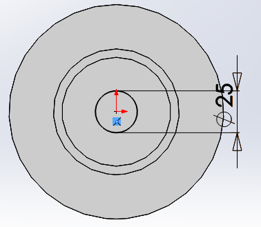
Adding Dimensions
 |
| Product of "Adding Dimensions" |
1) What action is taken in this step of the tutorial?
2) What is the first command in this step?
3) Where does step #3 tell you to move the mouse pointer?
4) What is the size of the dimension?
5) What is the unit of this dimension?
6) What is the final instruction in this step?
Extruding the Base Feature
 |
| Product of "Extruding the Base Feature" |
1) Complete this phrase: Extrude the 2D sketch to __________.
2) What is the first command of this step?
3) Where do the settings for the extrusion appear after exiting the sketch?
4) Under the "Direction 1" heading name the "end conditions" in the drop down menu.
5) After clicking on the green check-mark to complete this step, what appears in the.
FeatureManager design tree in the left panel?
FeatureManager design tree in the left panel?
Saving The Part
Before you complete this part of the tutorial you need to create a folder on your computer. Name the folder "SolidWorks files". When you save a file in SolidWorks - make sure you save it in this folder so you can find it later.
There are several different ways to "solve this problem" - so do what-ever works for you, just be aware that you need to have some type of system that works for you whether you are in class or at home.
If you use "different computers" you may want to consider a "flash-drive". At any rate you need to experiment with this so that you will have access to your files during class on a Tech computer as well as when you are on your own personal computer.
1) What is the "file name" for this part?
2) What file "extension" is added to this file name when you save it?
Sketching The Boss
 |
| Product of "Sketching The Boss" |
1) What plane is selected after you click on the "extruded Boss/Base" icon?
2) Does the "top" icon in the standards views toolbar provide you with the same view as
clicking on the "Normal to" icon?
3) On which toolbar is the "circle" icon located?
4) In step #5, explain the meaning of how the pointer changes when you point over the origin.
Dimensioning the Boss Sketch
 |
| Product of "Dimensioning the Boss Sketch" |
1) What is the first command in this step? Smart Dimension
2) What is the value of the dimension in step #4? 75 mm
3) Is the dimension that you modified a length or is it a diameter? diameter
Offsetting Entities
 |
| Product of "Offsetting Entities" |
1) Complete the phrase which appears on the "fly out" message when you move your mouse
over the "offset Entities" icon. "Adds sketch entities by offsetting faces, edges _______.
2) After pressing the "offset Entities" icon, list the "check box" items that appear in the left panel.
3) What is the offset distance in step #2?
4) What should the status of the "reverse" check-box" be before you click the green check-mark?
Extruding the Ring boss
 |
| Product of "Extruding the Ring Boss" |
1) Compete this phrase, "Now that the sketch is __________, extrude the sketch to make the
________ ________.
2) Do you exit the sketch at the start of this step?
3) On what toolbar is the "Trimetric" icon located?
4) What is the value of the depth indicated in step #3?
Sketching The Hole
 |
| Product of "Sketching the hole" |
1) In which toolbar is the "Extruded Cut" icon located?
2) Which plane of the part is chosen to begin the sketch?
3) In this step of the tutorial, is the top view of the part the same as the "normal to" view?
Look at the yellow message that appears when you press the "Extruded cut" icon and answer
the following.
4) You are about to sketch a new feature on an existing sketch. What is statement #1 in this
message instructing you to do?
5) How many planes (surfaces) are available for you to choose before you begin?
Dimensioning the Hole Sketch
 |
| Product of "Dimensioning the Hole Sketch" |
1) How many "types of circles" does the circle command allow you to make?
2) Name the circle "types" referred to in the previous question.
3) What is the value of the new dimension in step #4?
Creating a hole
 |
| Product of "Creating a hole" |
1) Why is "exit sketch" the first command in this step?
2) List the main headings that are visible on the left panel after pressing the "exit sketch" icon.
Modifying and dimensioning Hole Wizard Holes
1) What is the size of the modified hole in step #1?
2) Though not stated directly, what is the first command in this step?
icon.
3) What is the modification that you are making in step #5 with the smart dimension tool?
A
point of confusion will be do I move the holes that I already placed in
the previous step or do I begin again with no holes as in the previous
step. You can actually move the ones that you currently have in place,
but not by following the steps in tutorial.
There are some extra steps that are required beginning with step #5 - they are as follows:
You will notice that when you press the "Hole Wizard" icon that the smart dimension tool is not
active. So you will need to take the following steps . . . DO NOT choose the "Hole Wizard" icon
A)
Right click the mouse on the inclined surface around the hole to be
moved - then press the edit feature icon on the resulting menu that
appears.
All of the holes will change to yellow and the "hole wizard" panel will appear in the PropertyManger design tree. Press the positions tab . . .
B)
At this point notice that the "smart dimension" icon is activated -
press it and click on the center of the hole you want to move then click
on the origin and enter the desired value. Repeat for each hole.

Adding Fillets
 |
| Product of "Adding Fillets" |
1) What does the "fillet" feature do to the part?
2) How many different "fillet types" are shown in the PropertyManager design tree?
Sketching the Tall Cylinder Extrusion
 |
| Product of "Sketching the Tall Cylinder Extrusion" |
1) What is the purpose of this step in this tutorial?
2) Which plane or surface of the part is selected in step #2?
3) What type of line is used in step #4?
4) Where do you begin drawing the line indicated, what is the starting point?
5) How do you know that you have chosen the "right place" to start the line?
6) How do you know when and if the line is vertical?
7) How long are you instructed to make the line?
Completing the Tall Cylinder Extrusion
 |
| Product of "Completing the Tall Cylinder Extrusion" |
1) Which end of the line that you drew in the previous step do you begin the circle in this
step?
2) T/F The pointer changes when placed over the endpoint of the line.
Dimensioning the tall cylinder sketch
 |
| Product of "Dimensioning the tall cylinder sketch" |
1) What is the new value of the dimension modified in step #4?
2) What is the new value of the dimension modified in step #7?
Adding the Tall Cylinder Extrusion
 | |
| Product of "Adding the Tall Cylinder Extrusion" |
1) What is the purpose for this step?
2) What is the depth that you set in the PropertyManager under direction 1?
3) What is added to "selected contours" when you click on the circle?
Note that when you select contours - that you must "select" more than one area within the circle. Notice the figure below:
Sketching the Tall Cylinder Hole
 |
| Product of "Sketching the Tall Cylinder Hole" |
1) What is the first command in this step?
2) How is the "extrude cut" command different from the "Extrude Boss/Base feature?
Dimensioning the Tall Cylinder Hole Sketch
 |
| Product of "Dimensioning the Tall Cylinder Hole Sketch" |
Adding the Tall Cylinder Hole
 |
| Product of "Adding the Tall Cylinder Hole" |
Adding Fillets to the Tall Cylinder
 |
| Product of "Adding Fillets to the Tall Cylinder" |
 |
| Product of "Adding Fillets to the Tall Cylinder" |
1) Name the items selected to place the fillet.
Creating a circular Pattern
 |
| Product of "Creating a circular Pattern" |
The "view - Temporary Axes" is located as shown in the figures below:
1) How many tall cylinder extrusions are created in this step?
2) What tool is used to space the tall cylinders around the pressure plate?
3) What does the "Temporary Axes" command do?
4) After adding the number instructed, how many degrees are between each cylinder?
Adding the Last Fillet
 |
| Product of this tutorial |
1) What description appears in the PropertyManager design tree when you select the tow edges
indicated?
1) What items will the drawing you are going to create contain? 1) views, 2) center-lines,
3) center marks, 4) dimensions.
2) What does hiding transition edges mean? Hiding the edges between rounded or filleted faces
3) What is the size in inches of ANSI A Landscape? 8.5" x 11.0"
4) Describe what happens if you DO NOT hide the "hidden lines". The part shows hidden lines
in the views.
Creating a New Drawing
 |
| Product of "Creating a New Drawing" |
1) What items will the drawing you are going to create contain? 1) views, 2) center-lines,
3) center marks, 4) dimensions.
2) What does hiding transition edges mean? Hiding the edges between rounded or filleted faces
3) What is the size in inches of ANSI A Landscape? 8.5" x 11.0"
4) Describe what happens if you DO NOT hide the "hidden lines". The part shows hidden lines
in the views.
Creating a section View
 |
| Product of "Creating a section view" |
1) The sectional view on this step is through which "part" of the part? The center
2) Where is the "Section View" Icon located? Drawing toolbar
3) If desired, is there an option to reverse the direction of the section view? Yes
Creating a Detail View
 |
| Product of "Creating a Detail View" |
1) How is the center of the detail circle located? Move the pointer over the section view and
click to place.
2) How is the detail view "placed"? Move the pointer to place and click to add view.
Creating an Isometric View
3)
kkd
kkd
No comments:
Post a Comment